Temp & soil moisture sensor for plants with web based data acquisition - Peter Miller
Problem description and solution
The purpose of this project was to create an Internet of Things (IoT) weather station that also incorporated a soil moisture-monitoring component. The device is intended to notify the user when the moisture content of the soil drops below a certain value. To notify the user that the moisture content of the soil is too low, 3 LED’s, which correspond to the three soil moisture sensors, will turn on. The initial idea was to feed all of this data onto a server designed to handle IoT projects and then plot the data continuously. In practice I was able to record all of the data to a hard drive but was unsuccessful in streaming it to a web service. Because of this roadblock I have written a python module to read in and plot the recorded data with only a single input from the user. This project is also described in a state machine diagram (figure 1), which shows the workflow of the device.
Hardware and software solution
The atmospheric data is collected by a BME-280 breakout board, which was purchased from Sparkfun. The temperature is recorded in degrees C, relative humidity in %, altitude in meters, and atmospheric pressure in Pascal’s’. This breakout board has the capacity to transmit data using both the SPI and I2C protocols. For this project I used the I2C protocol because space on my breadboard and the connecting wires were finite commodities. Since this board required 3.3V, a logic shifter was needed to step the output signal up so that the 5.0V SDA and SCL serial ports on the Arduino can read the data. The original Arduino code for the BME-280 was borrowed from Sparkfun and modified to support three soil moisture sensors and the LED warning lights.
To measure soil moisture I had three Sparkfun soil moisture sensors (SEN-13322). The moisture sensor functions as a variable resistor where the voltage between the two pads is a function of the conductivity of the soil. The conductivity of the soil increases as the volumetric water content, or total volume of water in the porous soil increases. When connected to the analog input of the Arduino, these sensors only throw values between 0 (perfectly dry) and 900 (100% saturated) instead of 0 - 1023. And since the maximum saturation of soil is roughly equal to the critical porosity of the soil or ~50%, I defined a linear saturation scale between 0 and 100%. At 100% the soil is effectively a colloidal material (mud). A perfectly dry soil ideally has an output voltage of zero because the constituent minerals are non-conductive. The lower limit that I placed on the moisture content of my soil was 250 or 27%. At or below this value the light will start flashing indicating that the plant needs water. See figure 2 for image of setup.
A simple calibration was performed in order to convert the serial output from the soil moisture sensor to a percent saturation. The two soil end member cases (colloidal sand and dry sand) were measured to determine the minimum and maximum output values. Since the relationship between the output values and the percent saturation was assumed to be linear, the ratio of the output value to the maximum value was assumed to be the percent saturation.
Finally, to visualize the data I wrote a python module that sorts and plots the data collected from the atmospheric and soil moisture sensors. The module works only on CSV data files and allows the presence of a header. The plots generated are saved as individual pdf documents to a specified directory. For more information please see the commented code.
Issues
The two data collection systems all functioned properly, however, the final goal was to make this data available online through IoT services like Thingspeak or data.sparkfun. I was unsuccessful in interfacing the ESP8266 WiFi module with one of the services largely due to an inability to send the module AT serial commands programmatically. The ESP8266 module allows a microcontroller to access the local WiFi network through standard TCP/IP protocols. The AT commands pre-loaded into the firmware allowed me to access IoT services through direct user input as serial commands, however automating these commands proved elusive.
Next Steps
This device both collected data continuously for an extended period of time and functioned as an alert device if the soil moisture dropped below the specified value. As a concept device this project worked. However, there are a few steps (listed below) needed to make this an automated IoT device.
Consolidate wiring and modules onto a smaller board so that it will fit into a reasonably small waterproof case. The soil moisture sensors are waterproof and so they are able to function in the environment.
Fix the program for WiF connectivity. This is close to working but the issue of programmatically sending serial AT commands needs to be fixed and/or circumvented.
Generate an automated alert system that will either text or email the user when the soil moisture reaches a dangerous level for the plant that is being monitored.
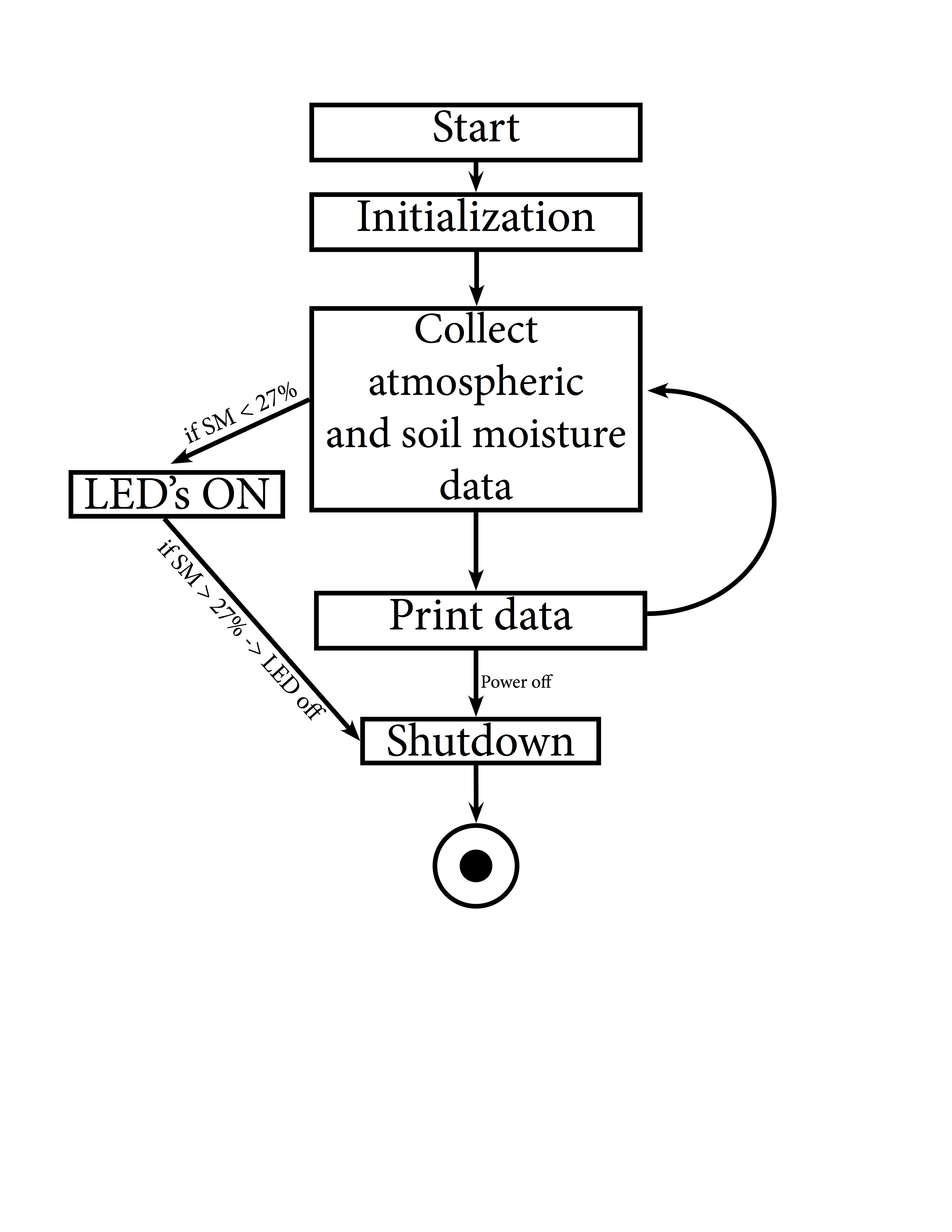
Figure 1: State machine diagram for soil moistures sensor. Once the initialization process takes place, the data is collected and the system checks the soil moisture. If it falls below the critical value of 27% then the LED attached to that sensor will turn on.
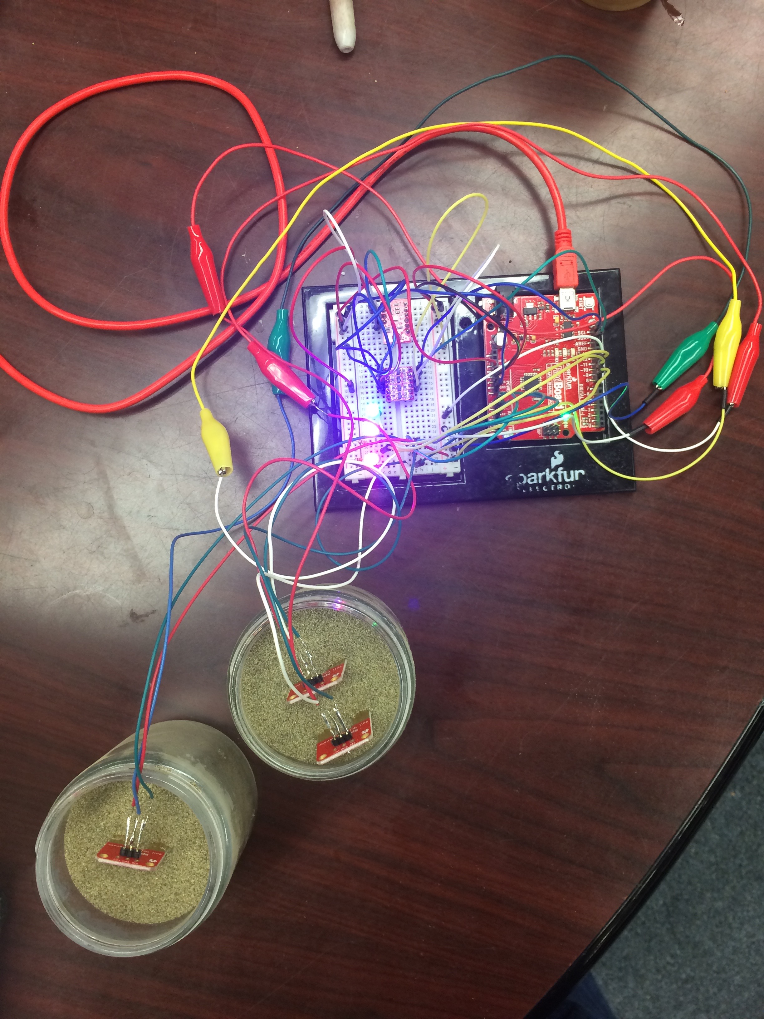
Figure 2: wiring setup between temperature sensors, soil moisture sensors, and the Arduino. The soil moisture sensors in this image are placed in the sand. The LED’s in this image are both signifying the sand is below the critical water content of 27%.