Automatic DCDT Calibration Device - Chas Bolton
Project goals
My semester project was aimed at improving our calibration techniques for the DCDTs. Currently, the technique for calibrating the DCDTs is done manually and is quite time consuming. In particular, to calibrate a DCDT one must mount the core to a vertical measuring device and clamp the outer part of the DCDT to a stationary ring stand. The user then moves the core in increments of 1mm or less throughout its entire voltage range. After one 1mm of displacement, the user must measure and record the voltage at this position. Again, this process will continue for the entire voltage range of the DCDT.
My goal was to improve the efficiency of this technique by creating a device that would automatically move the DCDT throughout its voltage range. Therefore, after the device is setup properly the only task for the user would be to simply record the voltage measurements. To carry out this task, I designed a holding bracket that would hold the DCDT and the bracket itself moves via a stepper motor that is controlled from a stepper motor driver and Arduino.
Design
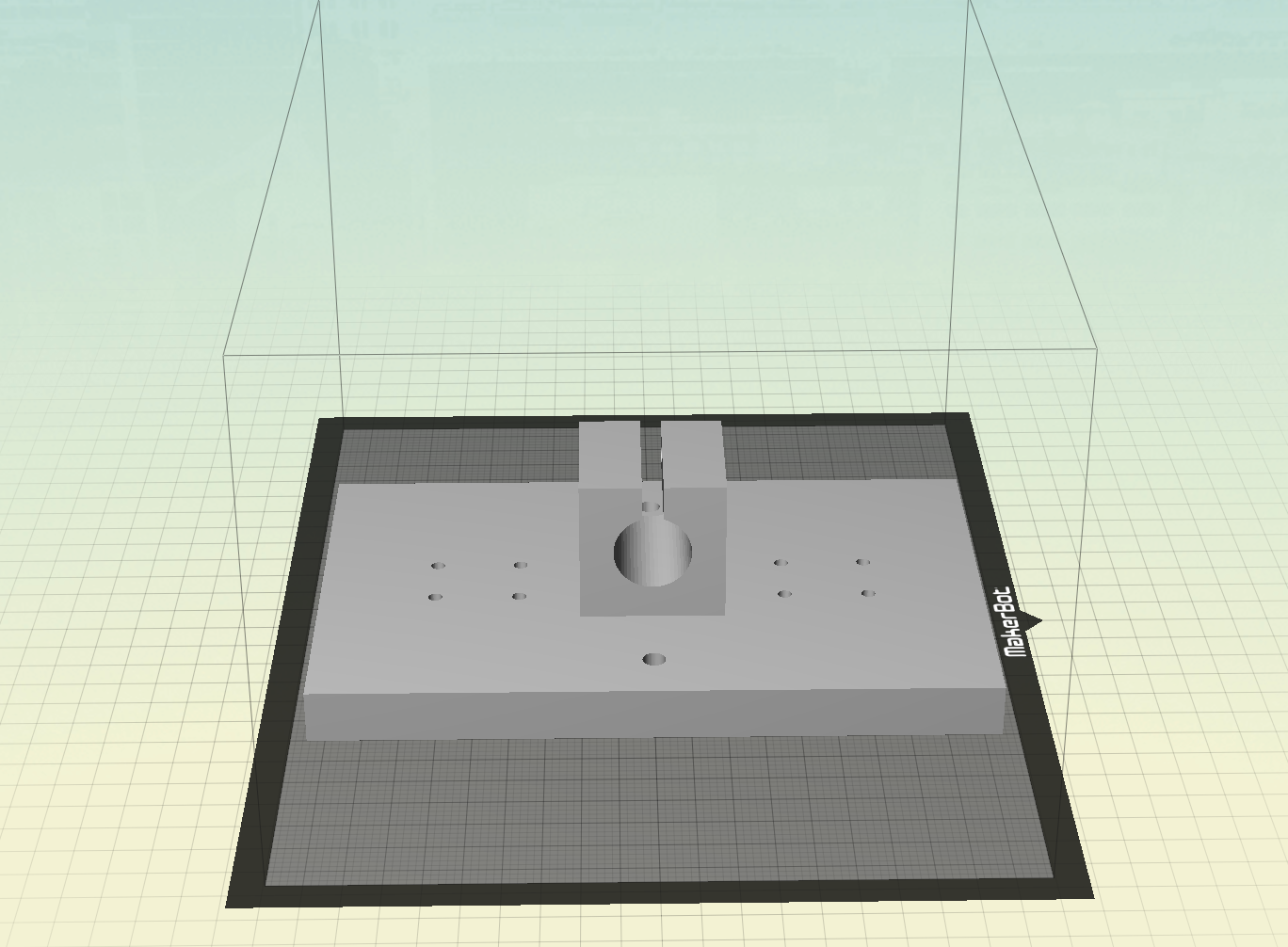
The first major design task was deciding how to hold and move the DCDT. To solve the issue of holding the DCDT, I came up with the idea of creating a holding bracket via 3D printing that would consist of a flat plate with a cylindrical holder mounted in the center of the plate that the DCDT could fit into.
To move the DCDT move up and down, I decided to mount the bracket assembly to two aluminum rods and allow the bracket to slide up and down the rods by a stepper motor, belt and pulley. To mount the rods to the DCDT bracket, I decided to use a set of linear ball bearings which would screw on to the bracket and would allow the bracket to move smoothly up and down the rods. The aluminum rods themselves would be mounted to a plywood frame.
The next step was deciding how to attach the belt to the bracket and how to mount the pulleys. I decided that the pulley could easily be mounted at the top of my frame via a U-bolt. However, once I started the assembly process I slightly modify this part. To mount the belt to the bracket, I decided to screw two I-bolts through the bracket and parallel with the cylindrical holder on the bracket. By using I-bolts, I could loop the belt through the I-bolts and tie them back into each other.
The final design task was deciding what material to build the frame with. I decided on using plywood, as this would be easy to work with and to mount things on. When deciding on the dimensions of the frame, I was primarily concerned with the height dimension due to the fact that the frame needed to be high enough to calibrate the DCDTs with long cores. A frame height of 2 feet was sufficient enough to accommodate this criterion.
Once I had an idea of how the project was going to work and what was needed to complete the project, I compiled a list of parts. The parts needed to complete my project consisted of stepper motor, a driver to control/drive the stepper motor, two aluminum rods, two linear ball bearings that the DCDT holder could mount to and slide up and down the rods, a belt, two pulleys, U-bolt, 2 I-bolts, and plywood.
Assembly
The DCDT bracket was the first part that I sought out to design. At first, I considered having the machine shop design the bracket out of steel. However, I soon realized that this would be too expensive and unnecessary for simply moving a DCDT up and down. Therefore, I decided I would make my DCDT holding bracket via 3D printing. Before creating the bracket in On-Shape, I hand sketched all the components of the bracket along with their exact dimensions. Once this was completed I created the bracket in On-Shape and 3D printed the assembly.
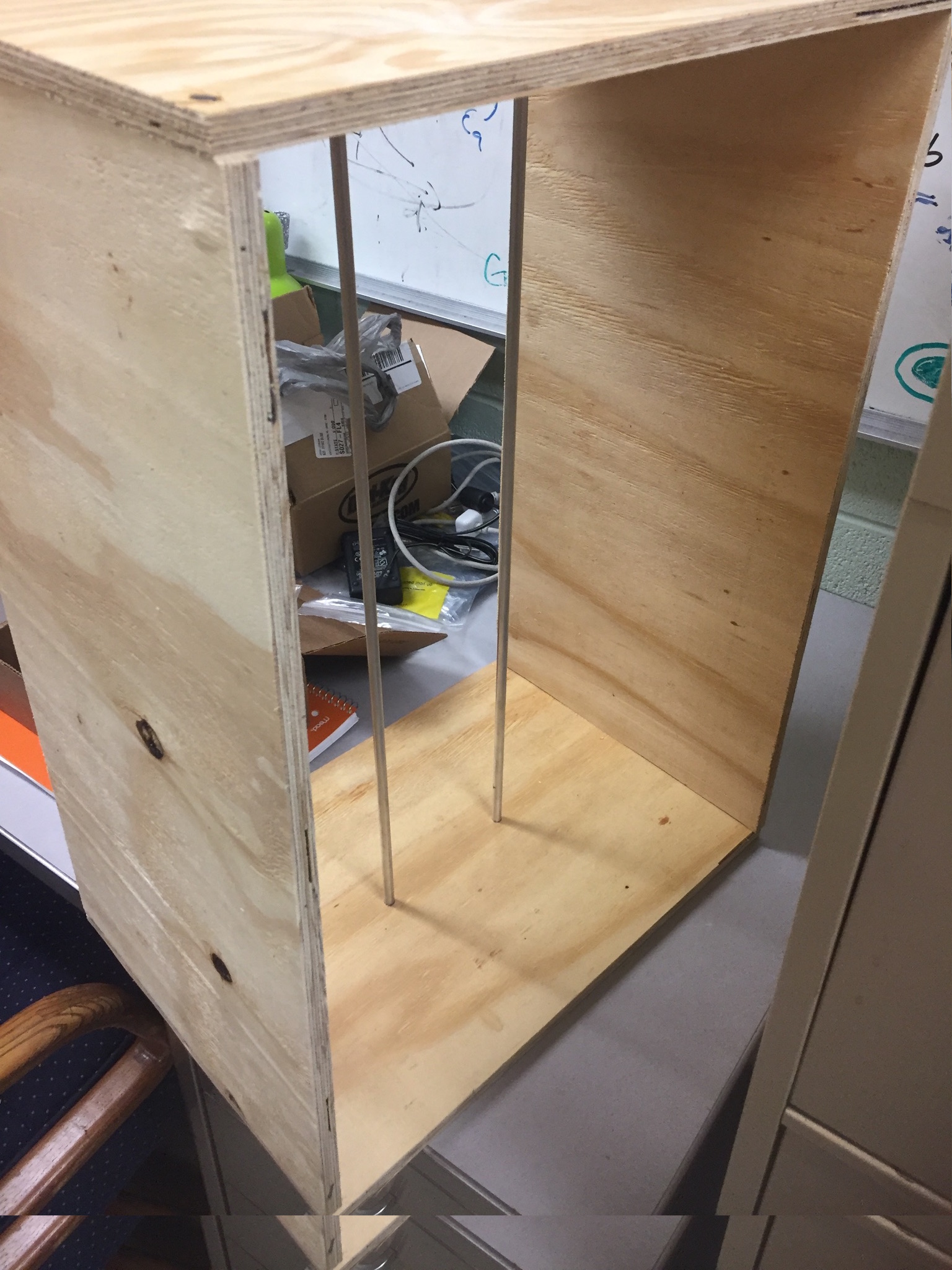
The next object I built was the frame. To do this, I used a jigsaw to cut the correct dimensions of
the plywood and then assembled a simple frame consisting of two base plates and two side panels. The top and bottom pieces of plywood are used for mounting the stepper motor, pulley and aluminum rods. I mounted the aluminum rods in the center of the frame roughly 11 centimeters apart by drilling two holes through the top piece of plywood and two holes in the bottom piece of the plywood. The top holes are drilled all the way through the plywood for the aluminum rods to slide through, while the bottom holes are drilled only half way into the plywood so that the aluminum rods can be held securely in place.
The next task was to power my stepper motor and driver. I first mounted my driver with a set of headers to the breadboard of the Arduino and powered it up through an external power supply.
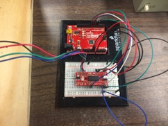
However, after doing this the voltages coming out the driver was inconsistent so I decided to solder the headers onto the driver. After soldering the headers on to the driver, the voltage readings come out of the driver were much more consistent. Once the driver seemed to be working properly, I modified an Arduino code such that I could move my motor in precise increments of 1mm and stop for 5 seconds and then move another 1 mm. After a total of 30 mm, the motor would then switch directions and move under the same conditions. To calculate the number of steps the motor must undergo for 1 mm of displacement, I used the following formula. Total number of steps per revolution/ total number of teeth on pulley times the pitch. Thus, for my assembly this equates to (400* 8)/2. The factor of 8 is due to the 1/8 micro stepping feature of the driver.
Once the motor was running properly and frame was built, I began working on connecting everything together to see if the project was actually going to work. I mounted my upper pulley to the top piece of plywood via a screw and two metal holding brackets. After the
belt and pulleys were properly assembled, I was able to run the first test to see if the project was actually going to work.
The first few trial tests turned out to be unsuccessful with making the bracket move. I began looking for issues with the design and noticed that the major problem was associated with the belt slipping on the pulley. My initial thought was that I was not supplying the motor with enough power. Therefore, I altered the power supply voltage and regulated the voltage coming from the potentiometer on the driver several times, but all to no avail. After assuming that it was not an electrical issue, I assumed that my problem could be a mechanical issue. Furthermore, I noticed that my belt was very loose and this might be the main source of error. After tightening the belt, the bracket began to move! However, it was still slipping and only moving in very small increments. Once I found this out I knew my problem was purely a mechanical issue. After thoroughly looking over everything on my frame, I noticed two other problems in addition to the loose belt. There was a slight misalignment between the two linear ball bearings that were mounted on the DCDT bracket and the top pulley mounted on the frame was not rotating smoothly and freely. Once I fixed these issues, the system started moving smoothly and the bracket was able to move up and down the aluminum rods in a continuous motion.
Currently, the automatic DCDT calibration device is able to move in smooth increments of 1mm, stop for 5 seconds and move another 1 mm. This process continues for 30 mm and the motor then switch directions. The idea of moving 1 mm is to ensure the voltage readings of the DCDT is linear with respect to displacement. The 5 second wait time is included to allow the user enough time to record the voltage measurements at a particular position. And the 30 mm, is around the average range of a typical DCDT. The idea of switching the motors direction is implemented make sure there is no hysteresis effect associated with the DCDT. All of these parameters can be changed by the user, and for a particular DCDT. For instance, not all DCDTs will need the full 30 mm range and this number can be increased or decreased. In addition, the user may need to increase the time it takes to read and record a voltage measurement and this can be done by simply changing the code to pause for 10 seconds.
Problems/Future work
The main problems that I encountered while working on this project were associated with the assembly process as mentioned above. If I were to continue working on this project to further its improvement there are a few modifications, I would make. First, I would redesign the upper pulley and belt system. As of right now, the belt has too much slack. I think the system would move much more smoothly if the belt was tighter. This could be done by implementing a spring the pulley/belt assembly. Also, I would consider reducing the size of the top and bottom portions of the frame and perhaps reducing the height of the side panels. As of right now, the frame is burdensome to move around and to work with.