Deformation-measuring Module - Chaoyi Wang
Abstract
A simple force measuring automation system is constructed to measure the deformation (strain) from a wooden cantilever bar structure. The system consists of two Arduino Uno boards with corresponding circuits, a servo motor connected to a wooden arm, and a cantilever-shaped load frame, a wooden bar is then pulled by the servo motor via the wooden bar through an elastic string. Specifically, one Arduino Uno board is programed to control the servo motor, the other Arduino Uno board is programed to register strain signals from the attached strain gages; the motion pattern of the servo motor can be either controlled by the swipe potentiometer or by pre-written scripts on computer; the strain gages are constructed with full-bridge configuration. As the servo motor pulling the wooden bar, the deformation and resultant force can be either observed from the LCD display on the Arduino Uno board or from the computer screen. This simple force-deformation measuring system is programed to be easily expanded and improved should there are more complicated applications.
Introduction
We measure all kinds of mechanical quantities in the rock mechanics lab, for instance, force, displacement, and acceleration, etc. Most of the measurement systems contain sensors and data acquisition systems. However, most systems are not self-sustainable, which means carrying out different test procedures automatically according to a pre-set scheme, giving out warning/shutting down the system automatically when necessary, and pushing notifications of test status to operators if the operator is not on site. Such automation is needed especially in long-duration experiments such as creep shear and slide-hold-slide.
Through this semester, we have learnt how to construct experimental apparatus from scratch, including building both hardware and software parts of the apparatus, signal conditioning, and data acquisition. In this project, a simple force measuring automation system is put together using the techniques learned from the class. The system consists of two major parts, hardware and software. The hardware part is composed of two Arduino Uno boards with preconnected circuits (one board controlling the servo motor, the other serve as a signal conditioner and data logger), a wooden load frame, a servo motor with a customized wooden arm, and a subject wooden bar which can be deformed by the servo motor. The software part is a piece of self-written program (LabVIEW), this program features functionalities of data displaying, conditioning, recording, and performing schematic loading sequences.
Combining the hardware and software part, this simple force-deformation measuring system is a prototype of more comprehensive-complicated experimental set ups used in rock mechanics laboratories. The system can be easily modified and expanded for additional functionalities.
Apparatus Configuration
Part 1. Hardware
- Load frame
The load frame is constructed out of oak and pine strips purchased from Lowe’s. The completed frame is shown in Figure 1.
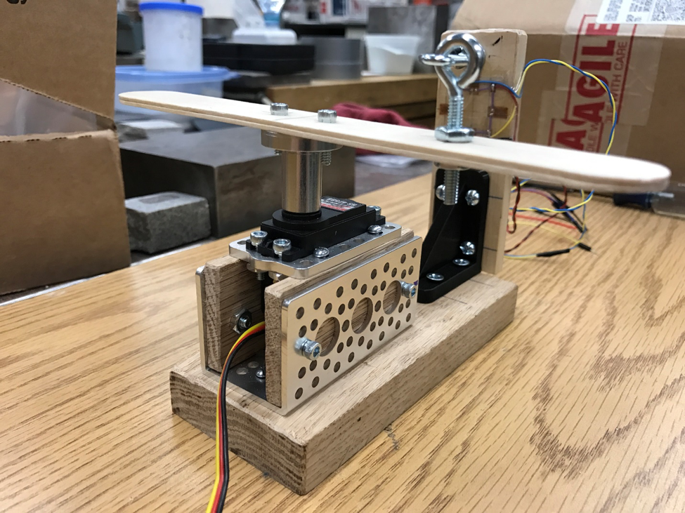
Figure 1. Load frame: the material of the bottom piece is oak wood; an aluminum servo motor holder is fixed by two screws on the bottom piece; the servo motor is hosted by a bracket and sandwiched between two pine plates as shown; the whole sandwich structure is then attached on the servo holder (a larger bracket) via two bolts on each side.
There is a bar holder also fixed on the bottom piece, this triangular shaped bar holder is made by 3-D printing (Figure 2), the design is fairly simple, the holder consists of two plates sitting perpendicular to each other with a supporting rib connecting each other. Since this part is 3-D printed, therefore the constructing material is filler plastic. One may question the stiffness of this bar holder due to its material, however, as we are going to deform a thin pine wood bar, the rib could provide adequate stiffness and support in this specific application discussed here.
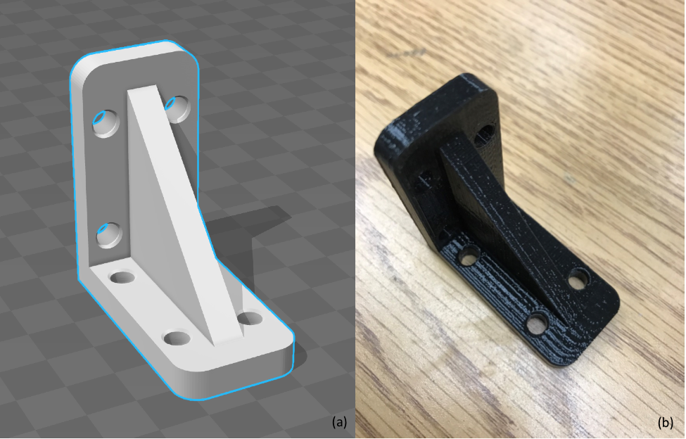
Figure 2. 3-D printed bar holder: (a) Onshape model of the bar holder; (b) 3-D printed sample holder.
- Wooden bar and strain gage configuration
The subject we are going to deform (bend) in this application is a pine wood bar (Figure 3). The dimension of the bar is NNxNNxNN. Four bolts are used to fix the wood bar to the bar holder though the configuration shown in Figure 3.
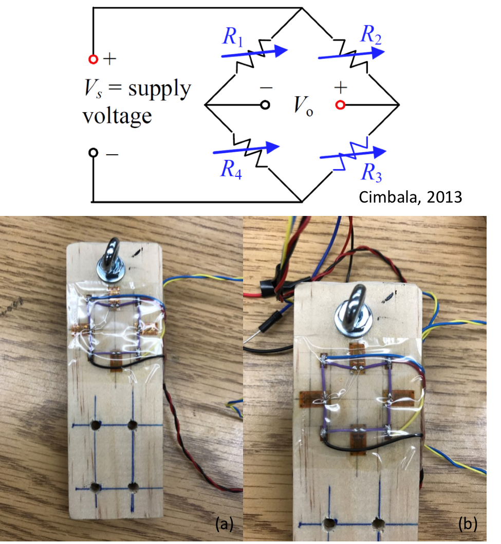
Figure 3. Pine wood bar used in this application: full-bridge configured strain gages are attached on the upper portion of the wood bar; four bolts are used to fix the lower portion of the wood piece firmly on to the bar holder.
- Servo motor
The model of the servo motor is Hitec HS-425BB (see the appendix for the link to the data sheet), the motor in assembly is shown in Figure 4. The maximum torque of this servo motor is 45.82/56.93 oz-in (4.8/6.0V).
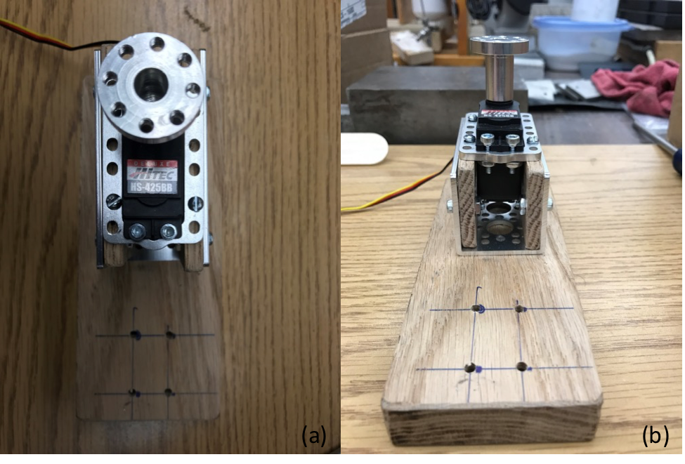
Figure 4. Servo motor used in this project: (a) top view of the servo motor mounted in bracket; (b) side view of the servo motor mounted in the bracket.
- Arduino Uno Board
There are two Arduino Uno boards used in this application, one Arduino board (AB1) is configured to control the servo motor and features a switch function from manual mode and programmed mode. To be specific, one can control the servo motor by slide the swipe potentiometer (voltage divider circuit) associated with the circuit, or control the servo motor by a set of pre-defined command scripts using serial communication. The other Arduino board (AB2) is configured as a signal amplifier and can register data to a personal computer. The two Arduino boards and the corresponding circuit is shown in Figure 5.
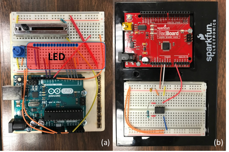
Figure 5. Arduino boards and corresponding circuit diagrams: (a) AB1, this Arduino is used to control the servo motor in manual mode (use the swipe potentiometer) or in automatic mode; (b) AB2, this Arduino board is used to acquire analog signal, amplify the signal, convert the analog signal to digital bits, and register the digital data onto a local computer.
Part 2. Software
- Data acquisition program
The data acquisition program “one_channel_serial_reader.vi” is written in LabVIEW 2015, the front control panel and the block diagram is shown in Figure 6 and Figure 7. This program can record data from the load frame to the local computer, and can read a script containing instructions for the servo motor to move.
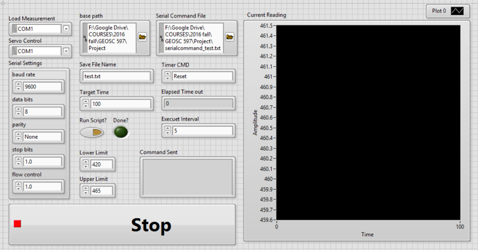
Figure 6. Front control panel of “one_channel_serial_reader.vi”.
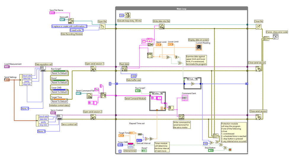
Figure 7. Block diagram of “one_channel_serial_reader.vi”.
- Servo motor control module
The servo motor is controlled either manually or by reading a pre-written file containing instructions to the motor. In the manual mode, the servo motor will rotate according to how much voltage is divided by the swipe potentiometer. The potentiometer is set in a voltage divider circuit, as shown in Figure 8, and the range of voltage measured from the two ends of the potentiometer is approximately 0 to 4.95 V.
If automatic control mode is chosen, the program will execute instructions form the command file one at a time according to a user-defined execution interval.
Experimental Performance
Part 1. Loading manually by a swipe potentiometer
By sliding the swipe potentiometer, the Arduino board will convert the voltage measured from the voltage divider circuit and map the value to a range of 0 to 180 degrees. The position instruction is then send to the servo motor to execute. The rotation of the motor is continuous, since the resistant change in the swipe potentiometer is continuous. The LCD display will display the approximate angle the motor has rotated. Figure 8 shows an image of LCD display while the motor is rotating in manual mode.
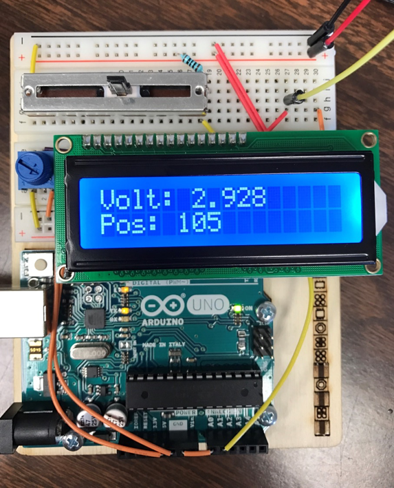
Figure 8. Servo motor rotates in manual mode.
Part 2. Loading automatically by a pre-written script
When choosing the automatic mode, the “one_channel_serial_reader.vi” program will read a text file containing serial commands to the motor. The commands are composed of a simple absolute degree value followed by a semi-column as a delimiter. A sample command file is shown in Figure 9.
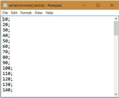
Figure 9. Sample command file “serialcommand_test.txt”: the file is composed of multiple lines of commands; each command contains a rotational degree value and a semi-column as a delimiter.
Part 3. Automatic shut down and overstress shut down threshold
The program can shut down by itself if certain criteria are met, such criteria are listed as following:
- The scheduled experimental time has been exhausted.
- The deformation reading exceeds either the pre-set upper limit or lower limit.
- Should any internal program error occur.
- The emergency stop button is pressed.
System Expandability
This system is a simple combination of hardware and software design in rock mechanics experimentation. The system can be easily modified or expanded either from software or hardware. The following example expansion scenarios are described:
- Hardware: the servomotor can be replaced by an actuator or continuous motor in different applications.
- Hardware: the wooden bar can be any material of interest such as rocks, polys, and metals. Under the assurance of higher stiffness of the sample holder.
- Software: timing modules can be expanded to accommodate not only uniform time interval executions but non-uniform timing schemes.
- Hardware and software: a cellular module can be added to the Arduino board 2, this cellular module can be programed to send out messages/emails to operator if the operator is not present onsite during automatic runs.
There are many more possibilities for this system to be expanded, however, due to the limited amount of resources, not all of them are described or addressed here.
Summary
In this specific application, a simple comprehensive automation system is built to accommodate the purpose of deformation measurements. The system consists of a hardware part and a software part, For the hardware part: a wooden arm driven by a servo motor pulls a wooden bar with an elastic string manually or automatically; the wooden bar is mounted on a 3-D printed bar-holder; full-bridge configured strain gages attached on the wooden bar are used to measure the induced deformation. For the software part: a LabVIEW program is developed to establish communication between the Arduino boards and a local computer; the program can register and record the deformation readings from the load measuring cell and control the servo motor by sending serial commands to the corresponding serial ports.
Acknowledgements
Hereby I want to express my sincere acknowledgements to Dr. Chris Marone and course instructor Dr. John Leeman for their patient instructions and inspiring lectures. And all people in the rock mechanics lab who tolerated me for doing wood work and making mess around.