3D Laser Profilometer - Srisharan Shreedharan
The problem:
Pre- and post-shear analysis of rock samples in any rock mechanics lab would be well complemented by including information about the surface roughness of the sheared sample. This is commonly achieved by 3D photogrammetry or laser profilometry. My project builds a low cost 3D laser profilometer which may ultimately be used to scan the sheared surfaces of intact rock samples at Penn State’s Rock Mechanics Lab. The scanner is a sub $30 prototype which will be improvised to incorporate higher resolution capabilities for use with smoother joint and fault surfaces.
Methods:
The product that I built is loosely based on two online instructables. The general principle behind the working of this profilometer involves the use of a line laser module and a webcam in tandem. The webcam ‘looks’ at the object that the line laser shines on and the code selects the ‘red’ pixels above a user specified threshold and saves them. Based on the distance between the webcam and line laser module, their distance from the object, and their respective geometric angles (as formed by the webcam,line laser and the object being scanned as vertices of a triangle), the code adjusts the point cloud to create a scan of the object.
I used the following resources for my project:
- Sparkfun RedBoard and associated parts (eg. jumper cables, breadboard etc.)
- 10k potentiometers x 2
- Line laser module
- Logitech webcam
- NEMA 17 stepper motor (200 steps/revolution or 1.8o resolution)
- TB6612 Stepper driver
- 100 uF capacitor
- Open source codes – Arduino 1.6.11 and Processing 3.2.1
Two broad mechanisms for the movement and position feedback are possible – seating the object to be scanned on a turnstile or moving the scanner (line laser and webcam) mechanism. I opted for the latter since it provides greater flexibility on the size and weight of the object to be scanned since it will neither be limited by turnstile size nor stepper motor torque.
To construct the mechanical side of the project, I took a plank of wood (33 cm x 5 cm x 2 cm) and named him Plank. I drilled a #20 pilot hole (11/64”) through the center of Plank (16.5 cm, 2.5 cm) and chiseled a side of it so as to get a ‘D’ shaped hole to snugly hold the NEMA 17 stepper motor’s ‘D’ shaped shaft. I mounted the line laser on one end of Plank and the webcam on the other end, with the RedBoard sitting at the center of my arrangement. Since the scanner had a weight imbalance as is, I added counterweights on the line laser side of Plank. The line laser was oriented perpendicular to Plank and the webcam makes a 20o-40:sup:o angle with it. A completely built prototype is shown in figure 1.
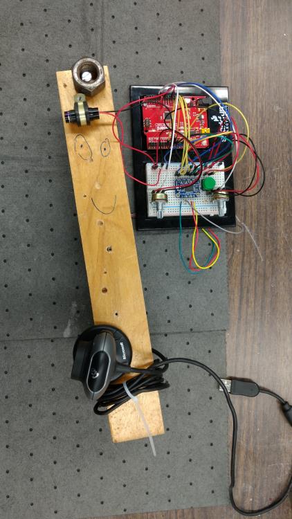
Figure 1: The completed mechanical build of the laser scanner
The electric build is relatively straightforward and figures 2 and 3 show the schematic and actual electric build I used in my project. The schematic shows an optional LCD screen that could have been used to see the speed and total angular movement of the device mapped to the two potentiometers, which I do not include in my project for lack of an I2C LCD. The schematic also shows the wiring for an A4988 stepper motor instead of the TB6612. I also include a button (not in schematic in figure 2) which restarts the device after each scan cycle if the user desires.
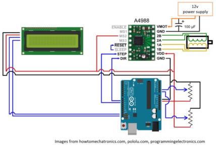
Figure 2: Schematic of the electric circuit
The Arduino code controls the physical aspects of the device. The device starts as soon as it is powered and steps from its starting point to a final angle (<360:sup:o) and a predefined speed, both of which are controlled by the two potentiometers. The scan occurs from 0 – final angle, at each step, after which the device steps back to its original position ‘0’. The processing of the scan occurs in a Processing sketch in tandem. The processing sketch A should be running during the scan sequence since it records the object’s reds as seen by the webcam and writes the coordinates into a file. Processing sketch B can be used after the scan to load the coordinates’ file, which it processes to provide a final point could of the scanned object. Sketch B requires the webcam angle relative to the laser angle (taken as 0 degrees) as an input.
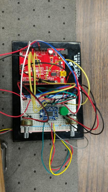
Figure 3: Actual wiring used in my project
Results:
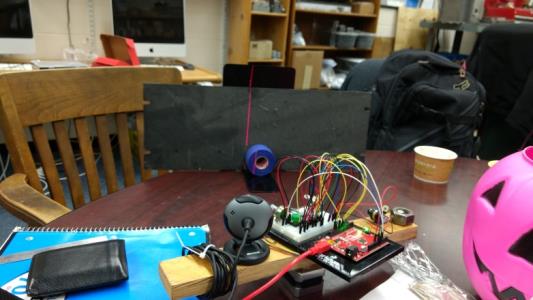
Figure 4: A laser scan of blue tape in progress
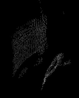
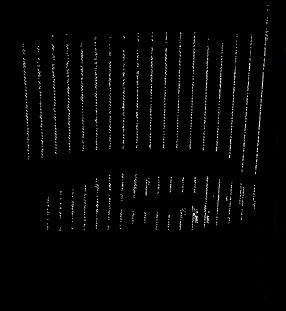
Figure 5: Two views of the scanned object.
Figure 4 shows a scan in progress, of a blue electrical tape, in the Rock Mechanics lab. Figure 5 shows the post-processed graphic render from Processing sketch B. The effects of distortion are apparent since the perfectly circular object appears to be elliptical. Features of the object itself, however, have been caught by the scan. The scan was carried out at a webcam angle of 15o relative to the line laser. Ideally, the red threshold can be increased and the scanning can be carried out in a dark room or enclosure to get better scan results.
Challenges:
I encountered the following ‘major’ challenges during my project:
a) The webcam does not capture very high resolution images, nor is its color contrast very good. Hence, it was hard to differentiate the reds of the laser from the spectrum of pink/orange-brown. Running the scanner in a dark environment or one with sharply different colors, such as a green, blue, white or black background solves this problem.
b) I could not get microstepping (pulse width modulating the driver) to work. As a result my resolution was limited to 1.8o resolution. This limits my ability to scan larger objects which I may not necessarily be able to bring very close to the laser.
c) Lens curvature and distortion was an aspect I did not anticipate (Figure 5). This requires additional corrections in Processing sketch B.
Future work:
As part of my future work, I plan to work on the challenges I encountered. Specifically, since I have a working proof of concept, I would like to apply for grants to get additional funds to build a working scanner with better resolution. Towards this end, I will master pulse width modulation and microstepping to obtain high resolution scans. I will also use a better camera and encase my setup in a dark box so that it is completely standalone for scanning small objects. I will also make my point cloud setup more user-friendly by using Python and creating a wireframe file that can be used with both 3D printers as well as for scientific analyses, by incorporating color gradients.
Instructables:
http://www.instructables.com/id/3D-Environment-Laser-Scanner-From-Scratch/
http://www.instructables.com/id/DIY-Arduino-3D-Laser-Scanner/