Syringe Pump for Injecting/Refilling Fluid - Yi Fang
Abstract
This report presents a process of identifying a realistic problem from daily experimental practice, designing the prototype and manufacturing the equipment for solving the realistic problem. A syringe pump was designed for long-term fluid injection/refill function. The syringe pump system is composed of structure elements, performing elements and control system. The structure elements are designed by free Cloud CAD suite Onshape and 3D printed by MakerBot at Penn State Library. The performing hardware (stepper motor, syringe and tubing) is purchased to perform injection/refill functions and the control system is designed using Arduino to control the hardware to inject or refill. The syringe pump prototype can be used to inject fluid and refill the fluid without unplugging the tubing and is suitable for cycled long-term injection/refill purpose.
1. Identification of Problem
1.1 Realistic Problem
Long-term fluid injection is vital for the success of in-house laboratory experiment. It is essential for pump to perform continuous injection. However, most pumps used in the lab experiments are commercial with limited volume (100 to 500 ml), in such a case, fluid injection may be disrupted because the tubing has to be unplugged from the running system and connected to reservoir for refilling (Figure 1).
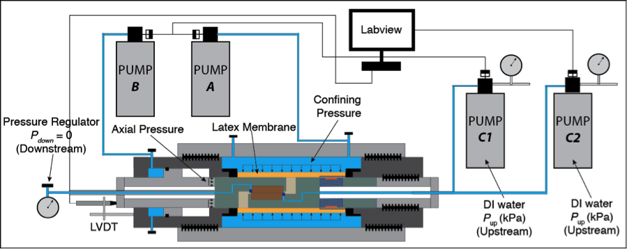
Figure 1. Schematic graph showing realistic problem: two pumps (C1 and C2) alternatively inject/refill the fluid.
1.2 Prototype and Simplification
The realistic problem can be solved by programming via Labview to accommodate two pumps alternatively injecting and refilling. To achieve the goal of this class - learn, explore and practice, a prototype of the realistic problem is developed to accomplish similar targets. Ideally, I would like to design a pump injection system composing of two syringe pumps that allow injection and refill acting simultaneously (Figure 2a). However, to reduce the budget, I performed a necessary simplification in which the number of pump is reduced to one and the injection/refill switch is performed by accommodation of one-way valves (Figure 2b).
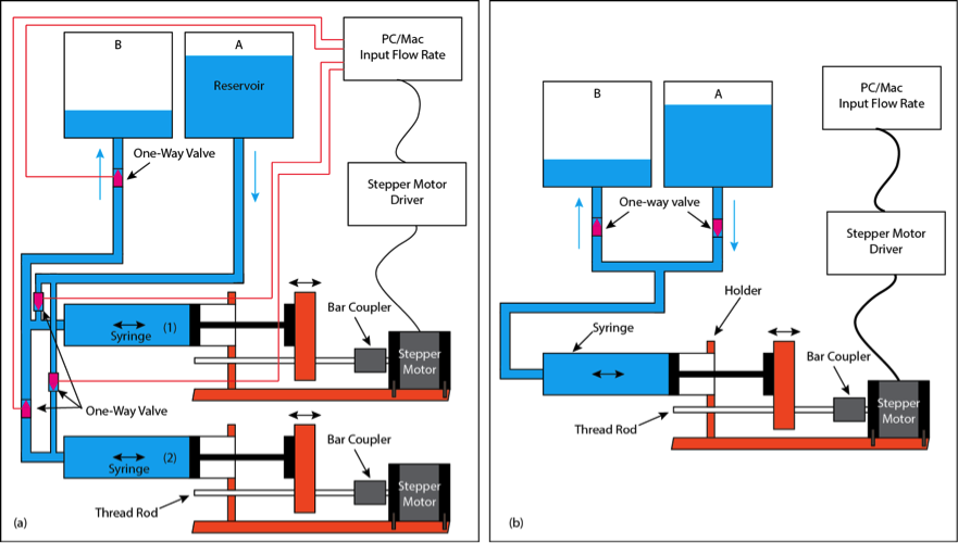
Figure 2. (a) Ideal version of syringe pump system as analogue to realistic problem (b) Simplified prototype of syringe pump system
2. Method
2.1 Pumping Hardware and Structure Elements
The pumping hardware is composed of a plastic syringe (20 ml), a stepper motor, a threaded rod with 4 nuts, a rod coupler, two one-way valves, one three way, a plastic tube and two plastic bottles, which are illustrated in Figure 3 and the budget of each component is listed in Table 1. The hardware is then assembled with the structure elements (Figure 4 and 5). The structure elements were designed by an online open-source CAD (Onshape) and were 3D printed by MakerBot at Penn State Pattee Library.
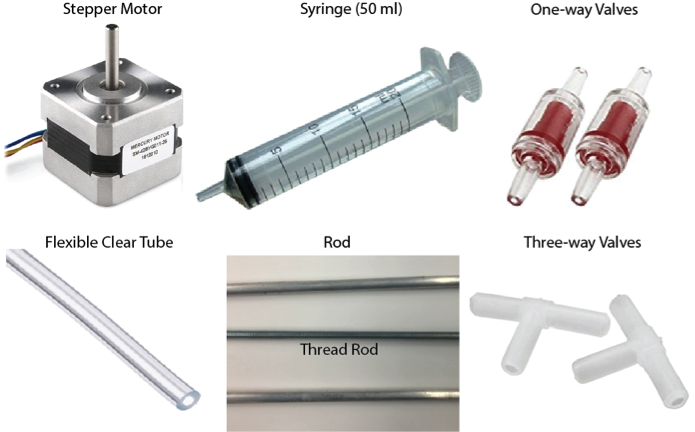
Figure 3. Major hardware component of syringe pump system
Table 1. Material and Budget
| Quantity | Item | Cost |
|---|---|---|
| 1 | Syringe with tubing | $8.97 |
| 1 | Stepper Motor | $14.95 |
| 1 | Body holder | $0 |
| 1 | Driving rod | $0 |
| 2 | Supporting rod | $0 |
| 1 | Two way tube | $5.67 |
| 1 | Plastic tank | $5.0 |
| 2 | Check valve | $24.16 |
| 1 | Three way tube joint | $0 |
| 1 | Wood block | $0 |
| 1 | Rod Coupler | $6.0 |
| 1 | Stepper Motor Driver | $14.0 |
| 1 | Thread Rod | $6.0 |
| 1 | Rod | $0.0 |
| 2 | Nut | $0.0 |
| Total | $84.75 |
Note: Those labeled as $0 are available in lab.
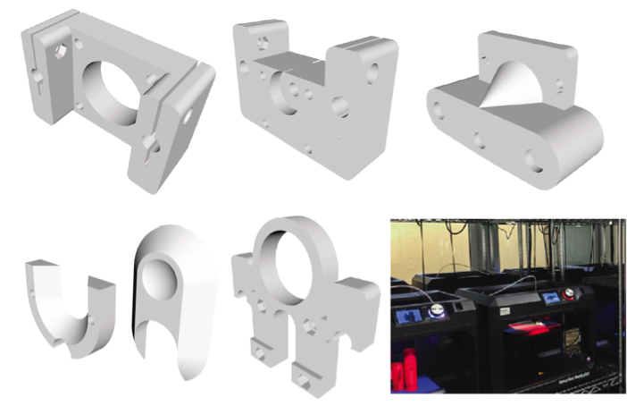
Figure 4. 3D geometry of structure elements
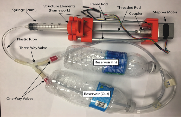
Figure 5. Assembled syringe pump system
2.2 Control System
The control system is composed of three parts: Arduino Redboard, Stepper Motor Driver and Arduino code (Figure 6). The Arduino code is first programmed and then uploaded to Arduino Redboad and Stepper Motor Driver. The commands are input via series monitor in Arduino software tools and are sent to Stepper Motor to perform the functions such as move forward or backward to control injection or refill of syringe. In this system, we developed four injecting flow rates (i.e., 0.585ml/s, 0.293ml/s, 0.146ml/s, and 0.074ml/s) based on the rotating rate of Stepper Motor (i.e., full, half, quarter, and 1/8th rotation rate). To send the command to the syringe pump, we use Arduino Series Monitor to input the desired injection/refill mode. Figure 7 shows the interface of Arduino Series Monitor, in which 9 injection/refill modes are listed for reference. Particualarily, for long-term injection-refill process, mode 9 is selected.
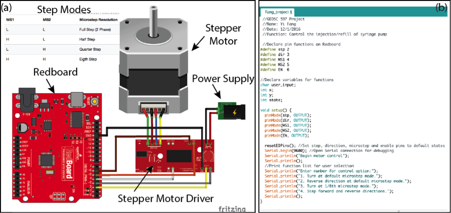
Figure 6. The Ardunio Redboard and Stepper Motor Driver together are used to send injection/refill command to the physical hardware (i.e., Stepper Motor) to drive the syringe
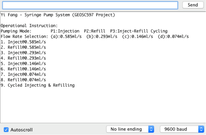
Figure 7. Interface of syringe pump control system
3. Challenges and Solutions
In developing the syringe pump system, following small challenging issues are encountered:
(1) Limited budget for solving realistic problem. To solve this problem, the simplest way is to simplify the problem. As shown in Figure 2, the realistic problem is simplified to an analogue version that still has the desired functions.
(2) Unmatched size between syringe and structure element: the problem was resulted from designing the structure element before syringe was purchased and delivered. This problem was easily solved by replacing the syringe with an appropriate size that matches the structure elements.
(3) Calculating and calibrating the flow rate: as no sensor is used to monitor the fluid volume, the only way to calculate the flow rate is by counting how much time it needs for syringe to pump out 20 ml water. In other words, this time is the same time that stepper motor needs to move forward a certain distance. After a series of tests, the precise flow rates are confirmed as illustrated in Figure 7.
Acknowledgement
I appreciate our lecture Mr. John Leeman for ordering the project hardware for me and for his great lectures and guide in the class. Thanks to Dr. Chris Marone for his kind help throughout the class.