Design for 3D Printing
When designing a piece of laboratory gear, there are many factors that have to be considered. This is even more true when the parts will be 3D printed as prototypes or as the final product. Due to the unique way that 3D printing produces parts, it imposes a special set of design constraints as well as a few design freedoms that may not be easily translated into a fully machined part. In this section we will go over some of these concerns and see how they are often addressed in the design and printing stages.
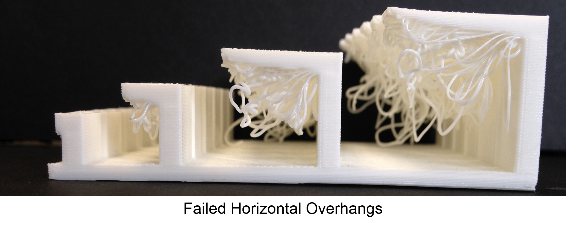
Overhangs
Any parts with overhang angles greater than 45 degrees from vertical should be supported or the print will most likely fail. External software generated supports may be added, or the designer may place temporary supports that are cleaned away after printing. It is also common to design permanent supports into the part that reduce any overhang angles to be less than 45 degrees. Using gussets and other features is a common way to accomplish this task. Printing a test piece is useful to get a feel for what your printer can do.
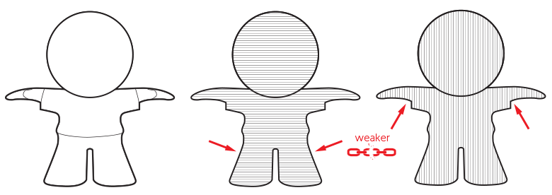
Layer Stress
3-D printed models are the weakest along the boundary between layers. Any parts that are expected to experience stress should be oriented such that the maximum stress is perpendicular to the printing layers (commonly called the z-axis).
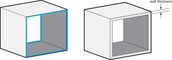
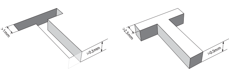
Wall Thickness
Too thick or too thin of a wall thickness on 3-D printed parts is a common failure mode and can increase the price of printing the part dramatically. Walls less than 1 mm thick are often weak, brittle, and print poorly. Walls thicker than several millimeters, are often unnecessary and are a waste of print time and material. Both of these increase the cost of the 3-D print significantly.
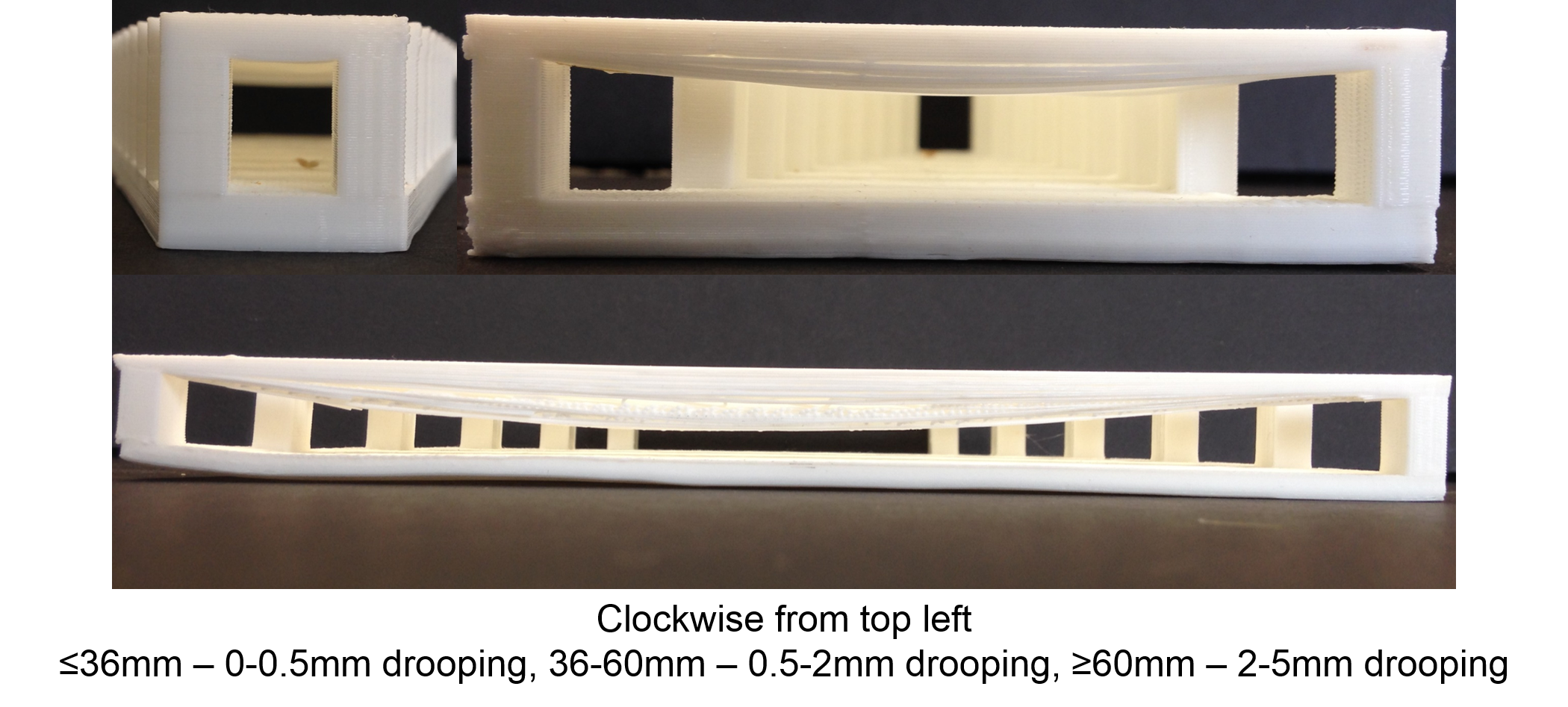
Bridges
Anytime the printer must print over open air is referred to as a bridging print. Bridging of more than a few centimeters often fails and results in sag of the print material. It is common for a 3-D print service bureau to be able to tell you what their maximum reliable bridging distance is. You can also do a bridging test print on your own 3-D printer to see what constraints you should follow.
..`(Image: utexas.edu) <https://innovationstation.utexas.edu/tip-design/>`_
Part Clearance
When designing parts that are meant to fit together, some clearance must be allowed. To allow a free fit of parts, a clearance of 0.015-0.020” is often enough. When designing parts for a close fit, a tolerance of 0.005-0.010” is generally adequate.
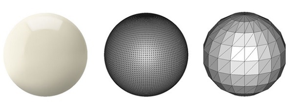
Resolution
When exporting your model to a stereolithography file for printing, make sure an adequate resolution has been selected. Too low of a resolution will result in prints that are angular and do not represent the shape you desired. More complicated models will take more time to slice and process, but will be a better representation of your 3-D model.
Text
Adding text to a 3-D print is a great way to label front panels, personalize an object, or make the user experience more intuitive. Text can either be engraved with letters recessed into the part, or embossed with raised lettering. Using engraved text is highly recommended because embossed text often has features that are too small at reasonable font sizes and result in failed prints. Engraved text also doesn’t leave material sticking up from the top of the part free to catch things and possibly be sheared off.
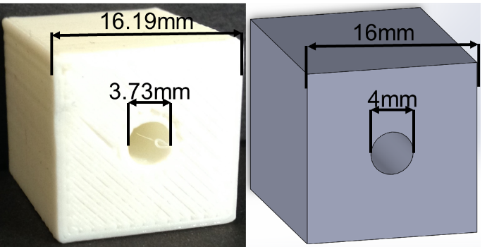
Dimensional Accuracy
Every 3-D printer has an accuracy specification in XY and generally a separate specification in the Z. You should consider these accuracies and the thermal contraction of the plastic if your part requires precise dimensional accuracy. There are several empirical formulas that have been developed for holes oriented horizontally or vertically in 3-D printed parts. It is easy enough to print a calibration print on your printer and create your own equation for your printer. Designing parts with enough tolerance in mind is generally possible though as 3-D printed assemblies are not specified to nearly as tight tolerance as machined parts. Also consider printing the part in a different orientation to get the highest dimensional accuracy where required. You can even split up the part into multiple pieces and assemble them after printing.
Model Verification
Your 3-D printed model could have errors when exported depending on your CAD package. Is important to be sure that the model is watertight and that no remaining internal geometry is left from doing Boolean operations on different shapes. Going through the sliced version of the model and looking for any incorrect internal geometries is highly recommended. Checking the generated mesh is easily accomplished with tools such as Netfabb or other printing and slicing software.
Internal Features
3-D printing allows you to design internal features and passageways that can be completely hidden from the outside, have bends internally, or embed other complex structures into the part. If your part will be machined by traditional processes at a later time, it is important to consider that these operations may not be easily achievable. Always design with the process that will generate the final part in mind.